
The Bottom Line
If you are controlling the speed of a DC motor, the best method depends on whether you need a fixed speed under varying load or a simple, adjustable speed for a known load. In most cases, PWM is the right choice because it controls average armature voltage without burning energy as heat. It works with both brushed and brushless DC motors.
For permanent-magnet DC motors, speed is approximately proportional to applied voltage, but the motor also slows when load increases because more current flows through the armature. If that speed drop is unacceptable, add closed-loop feedback. At the OEM level, this distinction often decides whether a cleaning machine can handle a heavy load or whether a pump keeps its flow stable.
We build DC motors and DC geared motors for this reason. The motor is only half of the package. The controller, gearbox, braking system, and feedback sensor all matter for final speed behavior.
Start with the Load Profile, Not the Controller
Speed control starts with a question: what is the motor doing when the load changes? On a sweeper, the brush motor encounters carpet, tile, and debris. On a pump, the load is relatively stable. On a conveyor, the torque can spike when boxes pile up. Each scenario changes the size of the motor and the type of speed control.
A typical line of thinking for an equipment engineer might be:
- Define the required output speed range at the driven shaft. A 250 W DC geared motor with a 20:1 gearbox may only give 50-300 rpm, even if the motor can spin faster.
- Identify the maximum load torque at the slowest speed. PWM keeps torque available, but the motor and gearbox must still handle the peak.
- Decide whether speed must stay constant when the floor condition, pile height, or fluid viscosity changes.
- Determine if the controller needs reversing, braking, or a soft start to protect the machine.
This load-based approach is common in industrial control applications where DC motors must work with conveyors, rollers, and pumps.
Four Methods for Controlling DC Motor Speed
There are four ways to change the speed of a DC motor. Each has a different trade-off between cost, efficiency, and speed range.
Supply Voltage Control
The simplest method is to change the voltage supplied to the motor. If you apply 12 V to a 24 V permanent-magnet DC motor, the no-load speed falls to roughly half. This is easy to test in the lab, but a variable DC power supply is too bulky and expensive for most machines. A linear regulator can reduce the voltage, but it dissipates the difference as heat. For a motor drawing several amps, that heat is unacceptable in a sealed enclosure.
PWM
PWM is the workhorse of DC motor speed control. A MOSFET or IGBT switches the supply on and off at a frequency from 1 kHz to 20 kHz. The duty cycle sets the average voltage. At 50% duty cycle on a 24 V supply, the motor sees an equivalent average voltage of about 12 V, but the current is delivered in pulses that maintain torque. The efficiency can reach 90% or more, because the transistor is either fully on or fully off.
An H-bridge makes PWM even more useful. It allows the output current to be reversed, so the motor can run in both directions. It also enables dynamic braking by shorting the motor terminals or regenerating current back to the supply.
Armature Voltage Control
Armature voltage control is the textbook method for separately excited DC machines. The field winding is supplied at a fixed voltage while the armature voltage is varied. This gives constant torque below base speed. For permanent-magnet motors, this method is simply another name for supply voltage control. In either case, the motor speed changes with the voltage, and the motor’s rated speed is the upper limit.
Flux Control
Flux control, also called field weakening, increases speed above base speed by reducing the field current. It applies only to wound-field DC motors. With a permanent-magnet motor, the field is fixed, so flux control is impossible. If you need speeds above a motor’s base rating, a larger motor or a different drive topology is usually the more practical answer.
| Control Method | Motor Type | Efficiency | Best Fit |
|---|---|---|---|
| Supply voltage (linear) | Brushed permanent-magnet | Low | Lab tests, low-power prototypes |
| PWM | Brushed and brushless | High | Cleaning equipment, conveyors, pumps |
| Armature voltage control | Separately excited wound-field | Medium | Industrial constant-torque drives below base speed |
| Flux control | Wound-field only | Medium | Higher speeds above rated base speed |
For a permanent-magnet motor, this means PWM is almost always the right starting point. The table above shows the difference in practical terms.
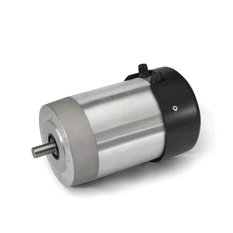
Open-Loop vs Closed-Loop DC Motor Speed Control
An open-loop PWM controller simply supplies the selected average voltage. If the load is light and stable, the motor speed changes very little. But when a load torque increases, the motor speed drops because the armature current and the voltage drop across the armature windings both increase. In a small permanent-magnet motor, that drop can be 10% to 30% from no load to full load. In some applications, that is acceptable. In others, it changes product quality.
A closed-loop controller adds feedback. A Hall sensor on a brushless motor provides a speed-related signal that the controller uses to adjust the PWM duty cycle. The controller compares actual speed to the set speed and raises or lowers the duty cycle. The result is a much flatter speed-torque curve. With an encoder on a brushed motor, the same approach works.
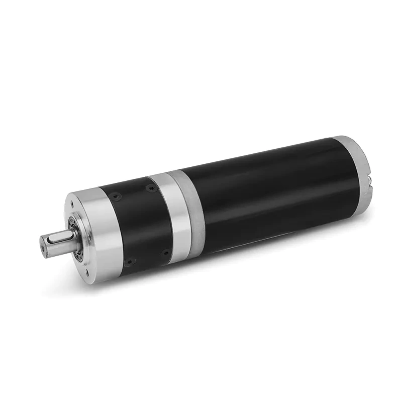
Brushless geared motors are especially easy to control in a closed loop because the commutation electronics already need rotor position information. Adding Hall sensors or an encoder is usually straightforward. If you choose a brushless geared motor with an integrated controller, the motor supplier may supply both power and signalling connectors, which simplifies the wiring.
When you are comparing motor options, look at the speed regulation spec. Open-loop brushed motors may be rated as plus or minus 10% across load; closed-loop brushless systems can hold a tighter band if the controller is tuned to the motor.
Choosing the Motor and Controller Together
Selecting a motor and a speed controller separately is common, but it creates compatibility problems. The controller must be able to supply the motor’s stall current, not just its rated current. A motor that is rated 1 kW at 3500 rpm can draw several times that current when starting. If the controller overcurrent limit is too low, the drive will trip every time the machine starts.
Voltage ratings must also match. A 48 V brushless motor cannot be run from a 24 V controller and still reach rated speed. Similarly, a controller with a 30 V maximum is not safe on a 48 V supply even if the motor is rated for it.
For geared motors, the speed range is defined at the output shaft. A motor running 3000 rpm through a 10:1 gearbox gives 300 rpm at the output. The gearbox also increases torque and slows the dynamic response. That is often an advantage, but it can make tuning the controller more difficult if the inertia is high.
A simple checklist for an OEM speed-control package should include:
- Continuous torque and peak torque at the output shaft.
- Rated speed range and the resolution of speed control you need.
- Supply voltage tolerance and current draw.
- Duty cycle and ambient temperature.
- Whether feedback is required and what type.
- Braking or reversing requirements.
- IP rating of the motor and controller.
- Noise and vibration limits in the final product.
Speed Control in a Real OEM Package
Take a battery-powered sweeper as an example. The brush motor is a permanent-magnet DC motor with a geared reduction. The supply is 48 V from a battery pack, and the brush speed must stay between 150 and 300 rpm when the brush hits different floor surfaces. An open-loop PWM controller would give a comfortable speed range, but the speed would drop on thick carpets.
Adding a Hall sensor or tachometer lets the controller compensate. The motor current rises when the load increases; the controller sees the speed fall and immediately raises the duty cycle. If the motor needs to be reversible, an H-bridge supplies that capability. If the drive must also stop quickly, dynamic braking can be part of the same controller.
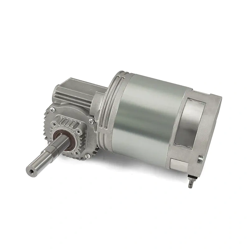
For a drive wheel on a mobile machine, the solution may be a motor transaxle that contains the motor and gearbox in one housing. The same speed-control principles apply, but the mechanical integration is simpler. In that case, the choice of controller is tied to the transaxle’s voltage and current ratings.
Final Considerations for Buying DC Motor Speed Control Components
When you describe your speed control requirement to a motor supplier, avoid giving only a voltage and a rpm number. The supplier needs the load torque at the required speed, the duty cycle, and the available supply voltage. With those values, an experienced manufacturer can recommend a motor, a gearbox, and a controller as a single package.
In our line of work, the most common mistake is choosing a motor that runs at the correct rated speed but cannot deliver torque across the full speed range. The second common mistake is choosing a controller with too little current headroom. Third, many engineers forget to check the motor’s thermal limit under continuous PWM operation at low speed, where the fan effect of the motor shaft is reduced.
If you are designing for cleaning equipment, logistics, medical devices, or industrial controls, control of DC motor speed is not a one-size-fits-all formula. It is a system decision. The motor, gearbox, feedback, and drive need to be sized together.

 English
 German
 French
 Italian
 Spanish
 Russian
 Polish
 Dutch